MTS-3 / the air-sensor build

Smart-building IoT

How it got here ↓

Drag to explore · scroll after clicking to zoom · dimensions reconstructed from photos

See the full enclosure studies

The build, over time

It started with a few wires.

The parts that changed, and the ones that stayed.

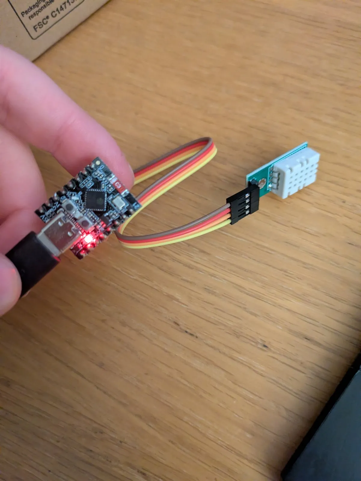
Early ESP32-C3 wired to a temperature and humidity sensor

01 / Loose wires

A sensor on the end of a cable

The first version was an ESP32-C3 and a temperature / humidity sensor joined by jumper leads. Small enough to get a reading, with everything still out in the open.

1 / 5
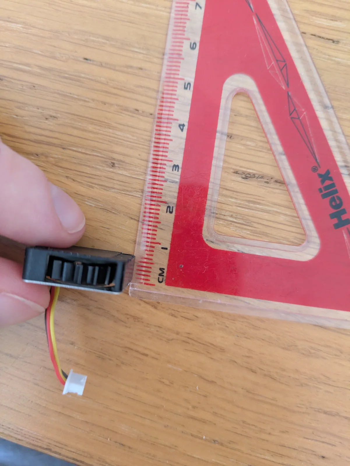
Still experimenting: the small blower and airflow tests are another branch of the build.

Current projects

Hardware + software · ongoing

From a room sensor to a connected home

A homemade room sensor, a view of the house, and a radiator that reports back when its setting changes.

Notes updated

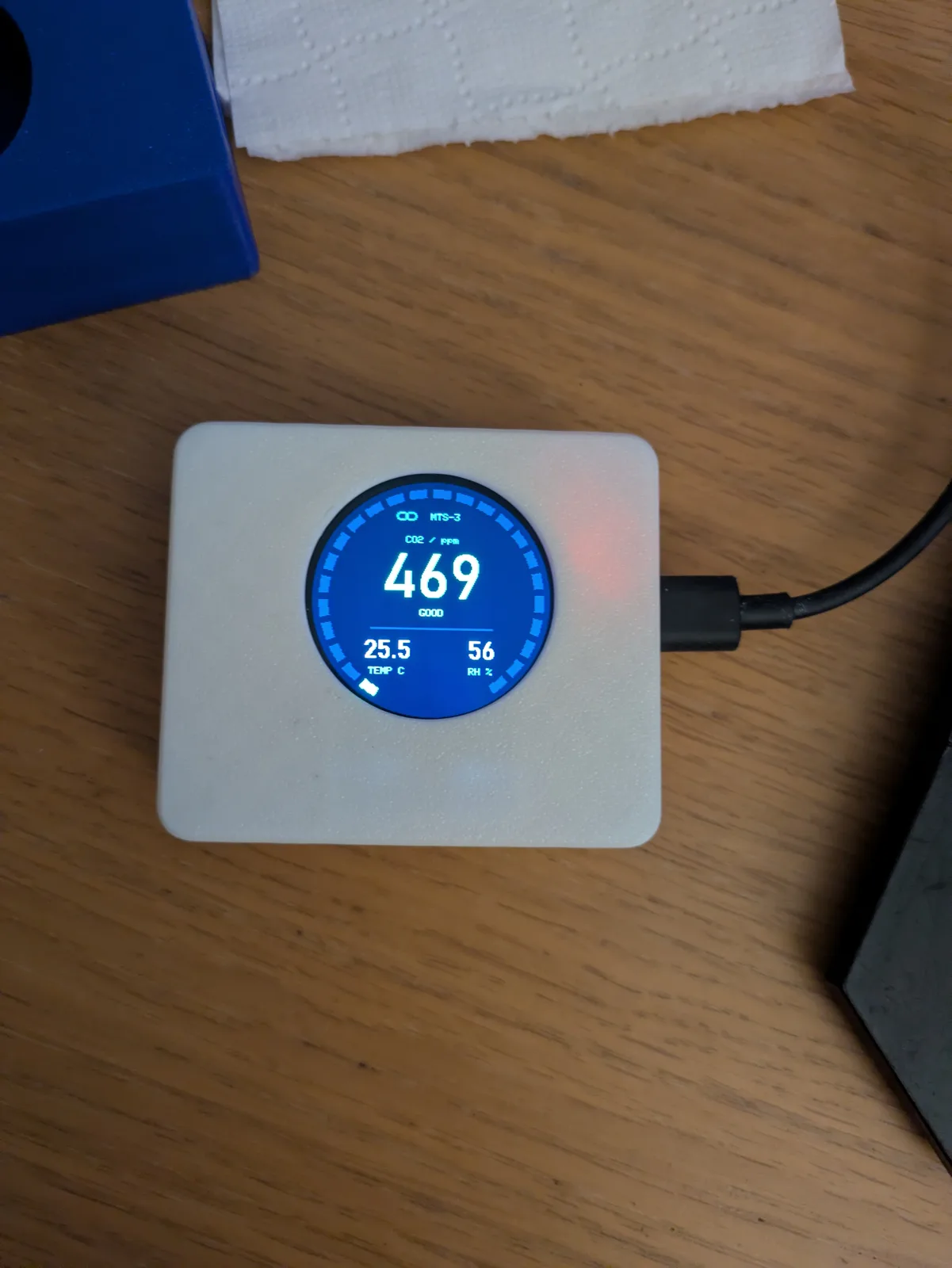
The white enclosure with the display running.

From the circuit board to the room view

A reading has somewhere to go.

The sensor is only one end of the project. AWS carries its readings into my dashboard — and carries settings back to the device.

On the device

MTS-3

Read the sensors

ESP32-C3 · SHTC3 · SCD40
AWS / connect

IoT Core

Receive pointset

MQTT · mutual TLS
AWS / processλ

Telemetry Lambda

Validate the message

Identity · points · values
AWS / retain

DynamoDB

Store the reading

Timestamped records
AWS / serve

HTTP API

Query latest + history

API Gateway · Lambda · Cognito
In the browser

My dashboard

Put it in the room view

React · hosted on Amplify
DEVICE → CLOUD → DASHBOARD

Each pointset message is checked and stored. The signed-in dashboard requests the latest values and history through the HTTP API.

Illustrative messages and timing. This graphic does not connect to the private dashboard or send commands to devices.

DBO / what a point means

A name that survives the journey.

Digital Buildings Ontology names describe the measurement, rather than the pin it arrived on. The device registry pairs each point with its units and allowed values, so the firmware, cloud and dashboard share the same meaning.

zone_air_temperature_sensor
Temperature · degrees_celsius
zone_air_relative_humidity_sensor
Humidity · percent_relative_humidity
zone_air_co2_concentration_sensor
CO₂ · parts_per_million

UDMI / how it is carried

Readings, settings, and a reply.

The implemented UDMI 1.5.2 message shapes separate measured pointset values, desired config, and reported state. It is a focused UDMI-style implementation, not the full UDMI toolchain.

Inside the pointset message Example JSON{site}/MTS-3/events/pointset

Where the messages become useful

The dashboard closes the loop.

The private sensor view brings together temperature, humidity and CO₂, selectable history ranges, reporting intervals and a message inspector. The wider room view puts those readings back into the house.

A setting is only shown as applied after a matching device-state acknowledgement. Publishing a configuration to AWS is one step; the device confirming it is another.

Hardware and software at a glance
Devices
ESP32-C3 nodes, one per room
Sensors
SHTC3 (T, RH) · SCD40 (CO₂)
Cloud
AWS IoT + serverless services
Interface
React view of both floors
Control
Terma radiator over BLE

PlatformA small building system

This started as a way of seeing temperature and humidity around a house. It grew into a private building view where each room can show its sensor readings, history, device state, and, where it makes sense, controls.

ESP32-C3 devices publish structured messages through AWS IoT. Serverless services validate and store the readings, while a React dashboard puts them back onto the two floors of the house. The same path carries configuration in the other direction.

  • ESP32-C3
  • MQTT
  • AWS IoT Core
  • Lambda
  • React
  • Bluetooth LE
  • Each physical device has its own identity and certificate.
  • Readings keep their device, room, timestamp, and units attached.
  • The interface distinguishes a requested change from one the device has actually applied.

HardwareThe air-sensor node

The first version paired an ESP32-C3 with an SHTC3 for temperature and humidity. I later added an SCD40 CO₂ sensor on the same I²C bus and carried the new reading through the firmware, device metadata, cloud services, history charts, and room view.

The deployed device reports temperature, humidity, and CO₂ using the point names and units expected by the rest of the platform. The board is still deliberately homemade: protoboard, short wiring runs, and a printed enclosure that can be opened again.

Early ESP32-C3 temperature and humidity sensor connected with jumper wires
The wired prototype that came first.
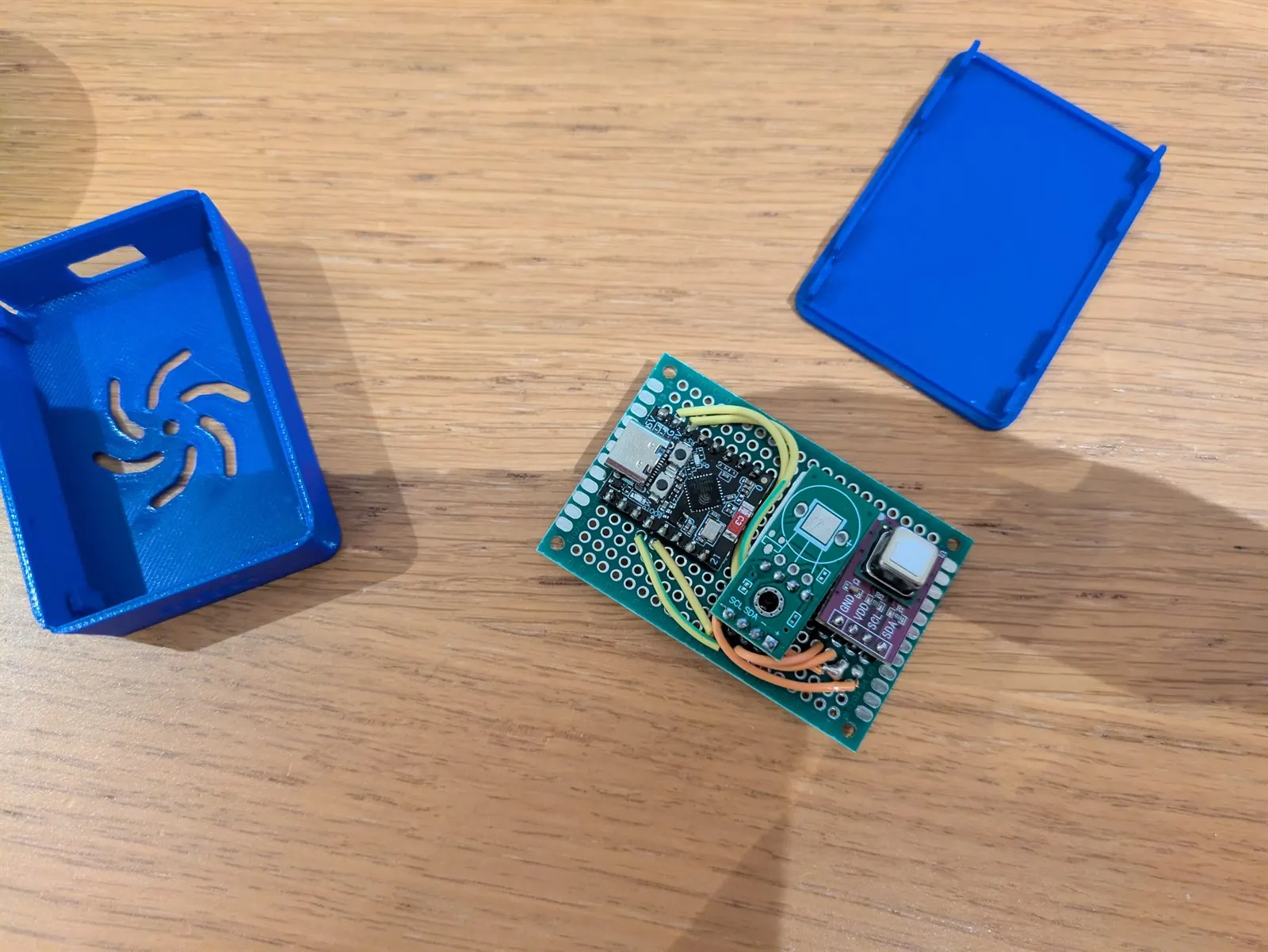
Compact ESP32-C3 and SHTC3 sensor node on protoboard
The compact temperature and humidity node.

From the bench · September 2026

The white enclosure is the current setup. Blue prints record the earlier fit checks and blower experiments.
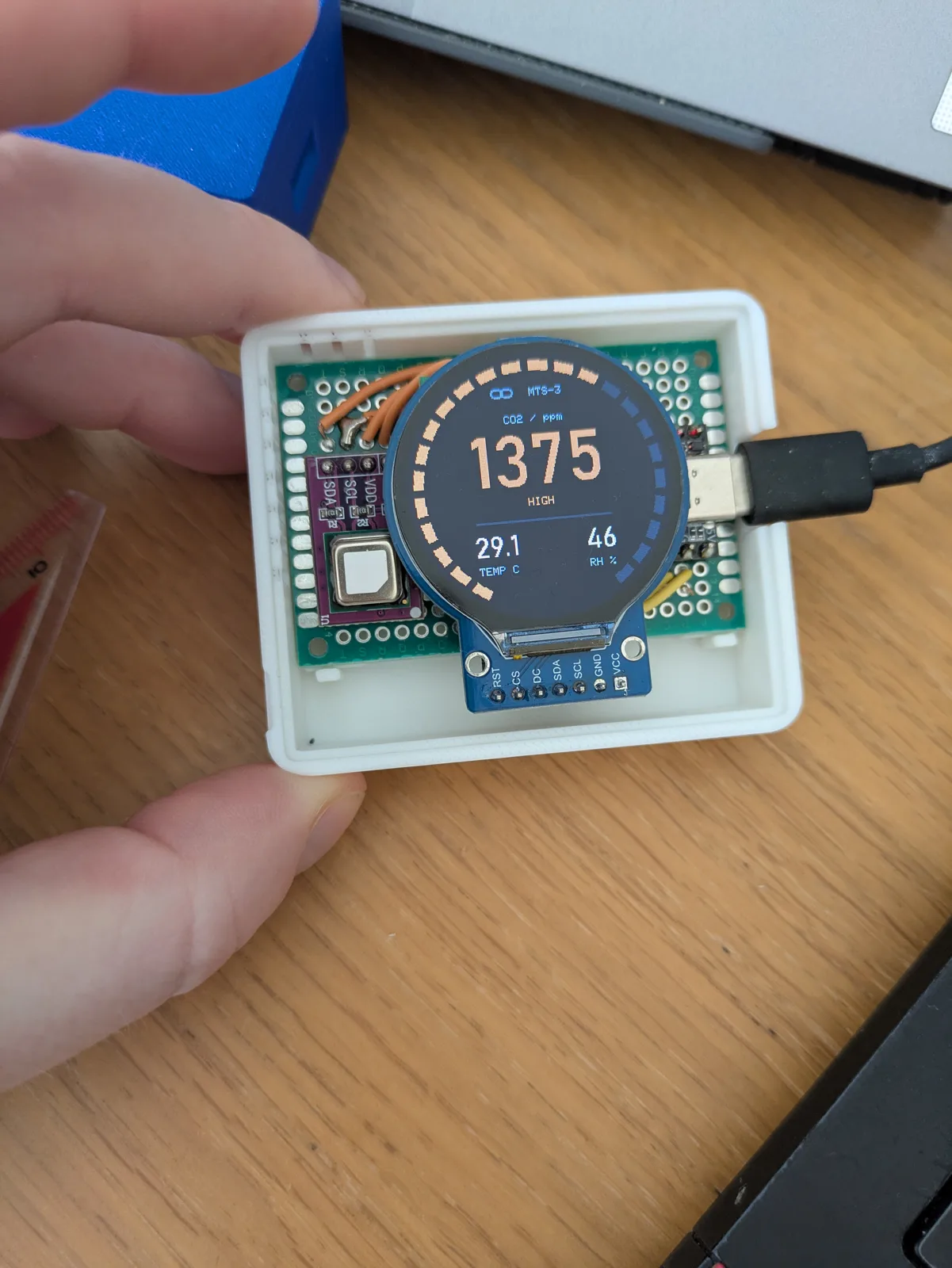
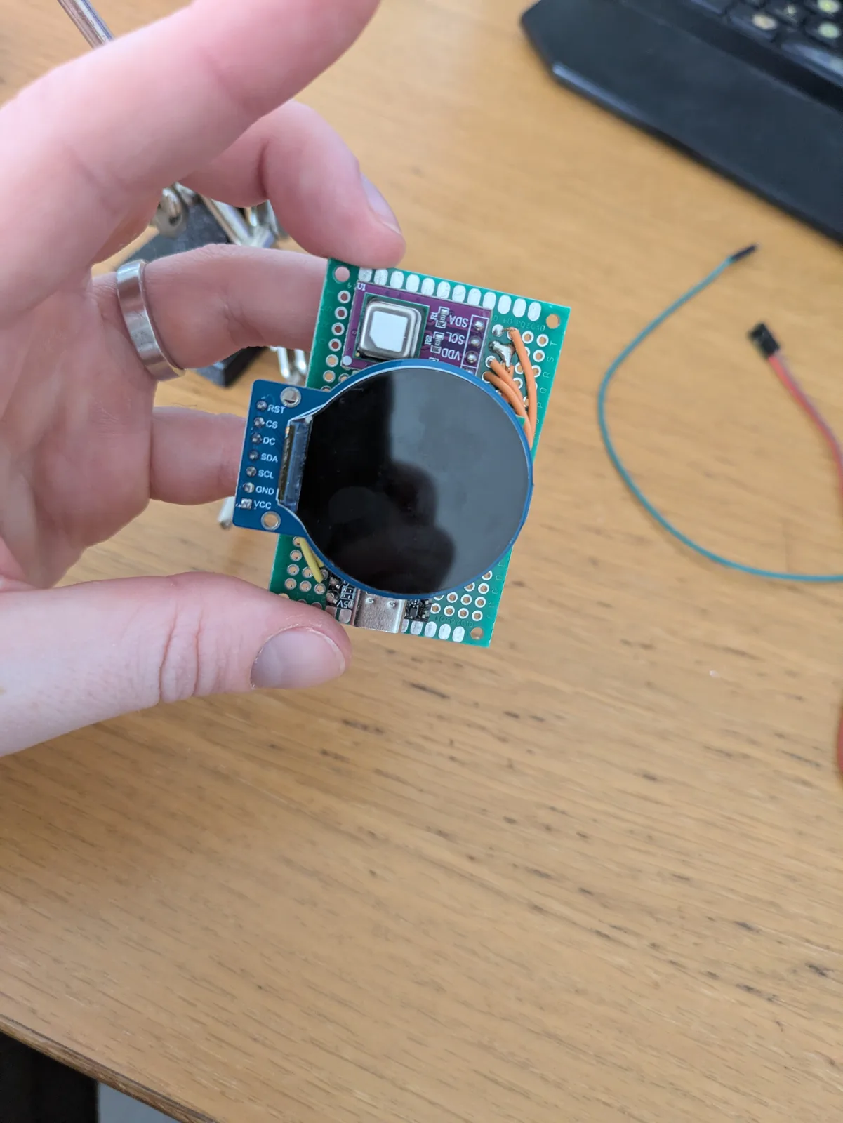
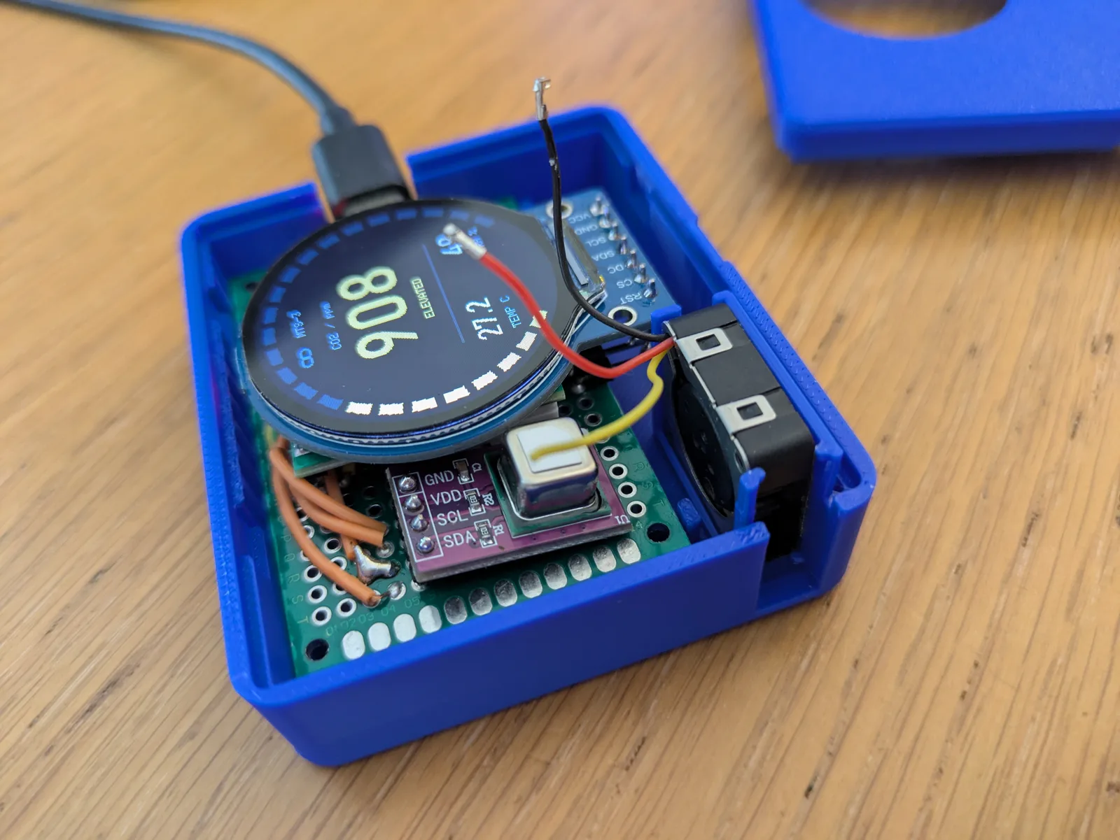
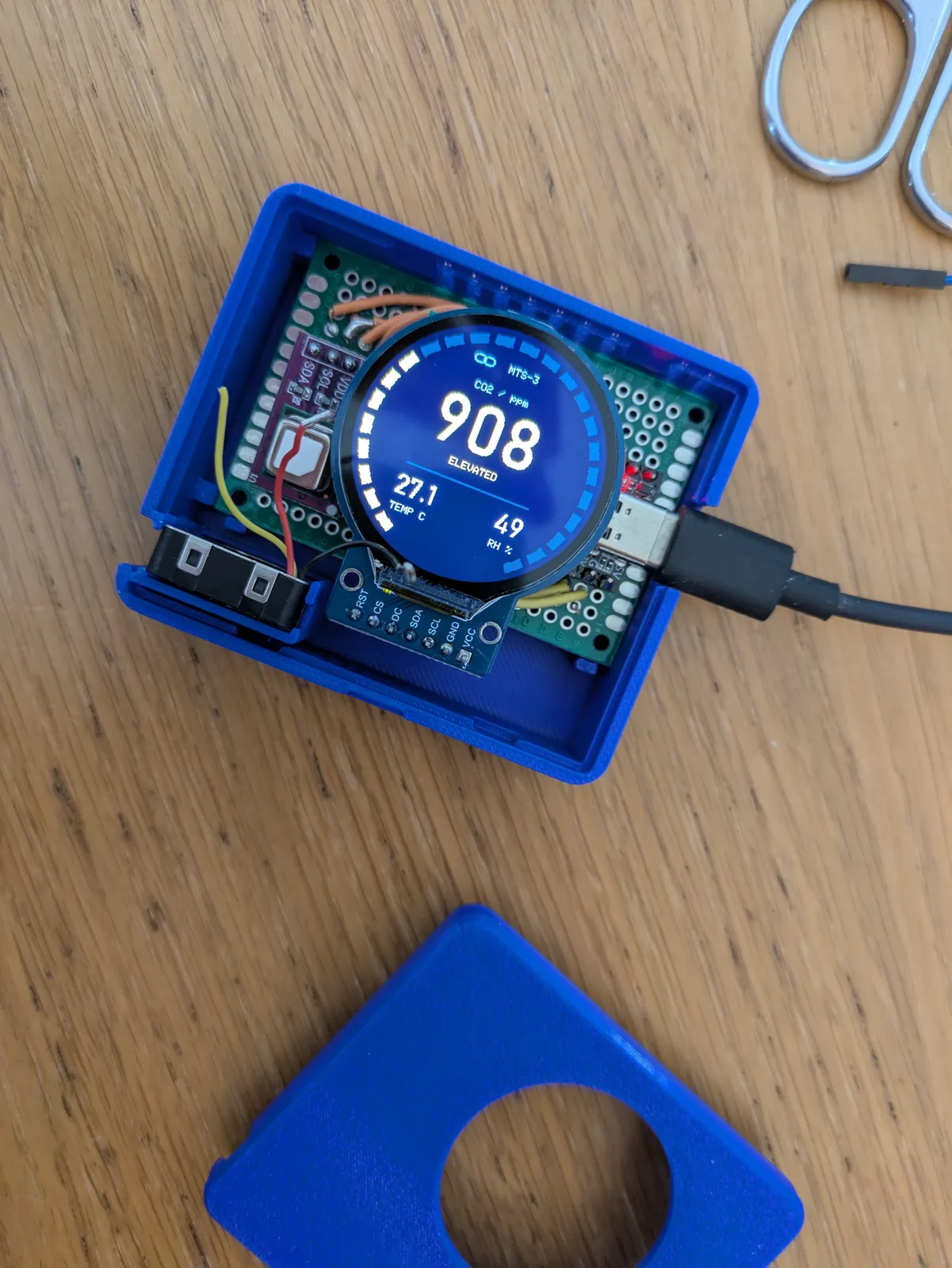
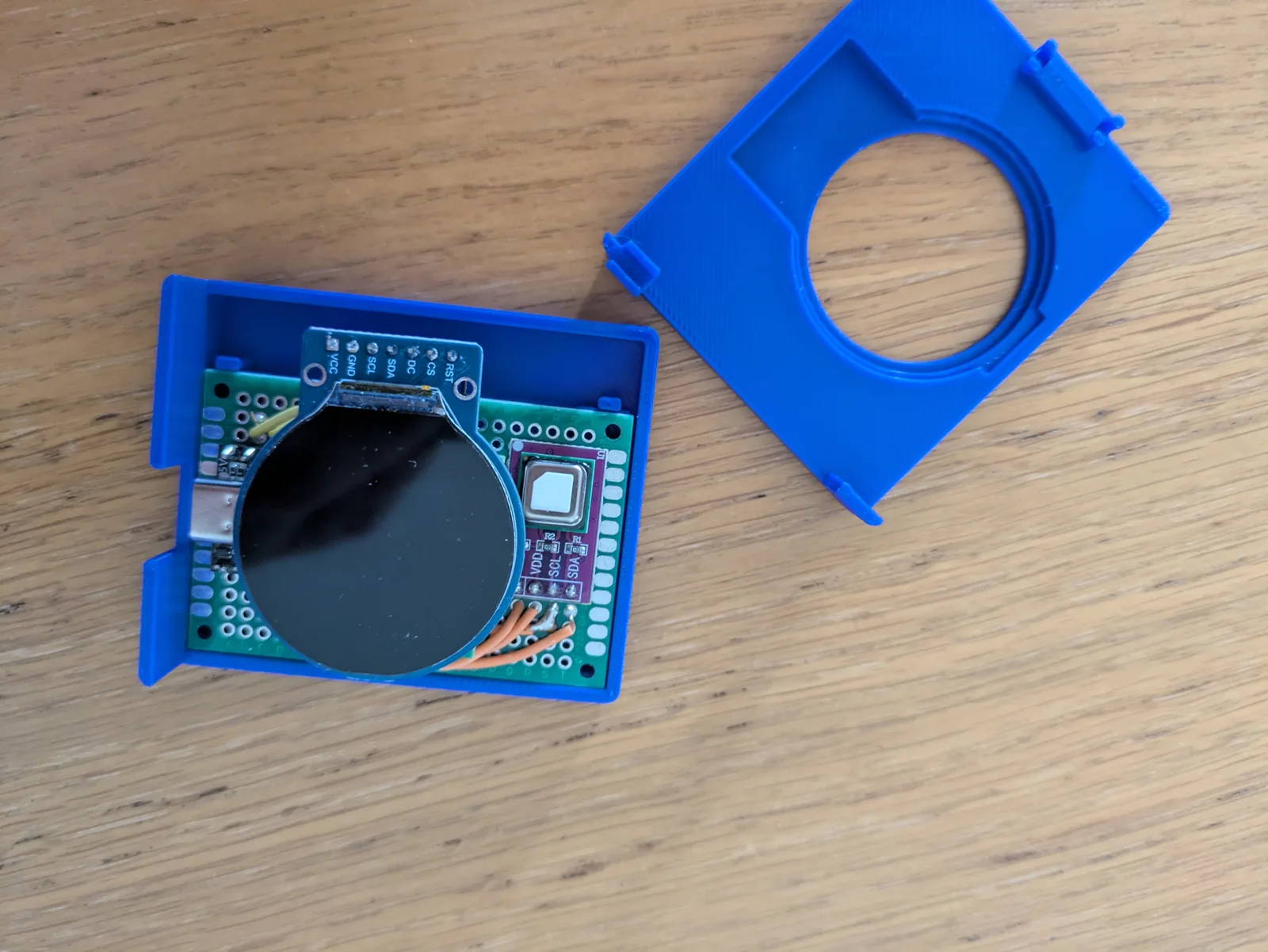
Inside the white enclosure: display, sensors and USB-C.
The assembled electronics before fitting the case.
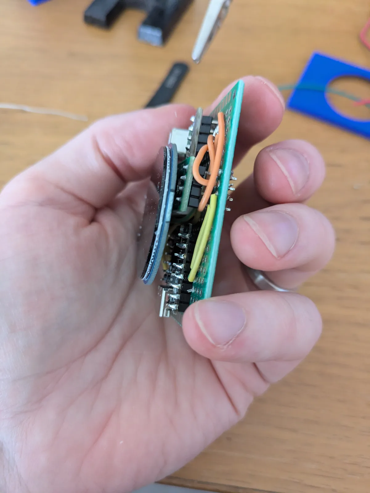
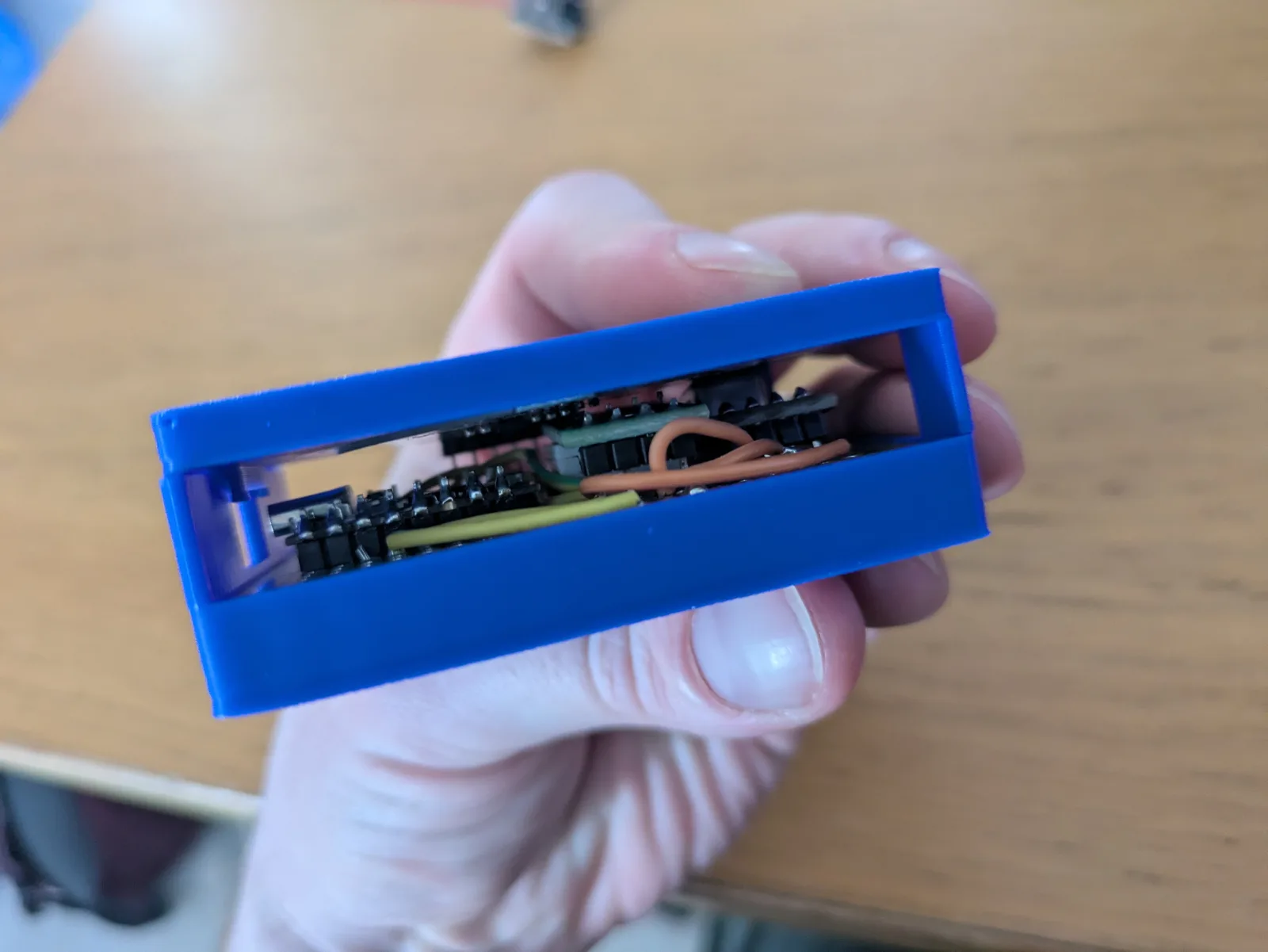
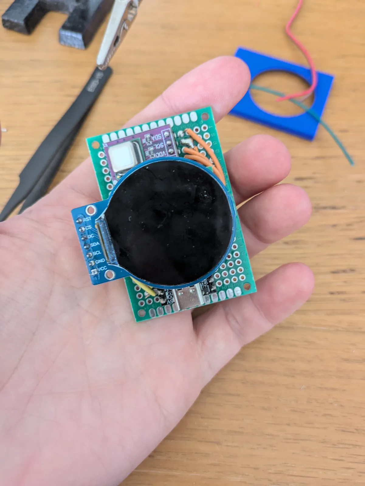
Side view of the display and board stack.
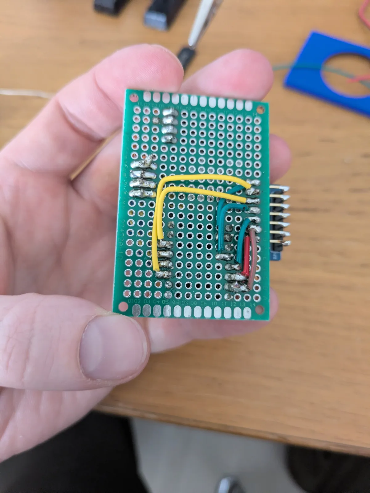
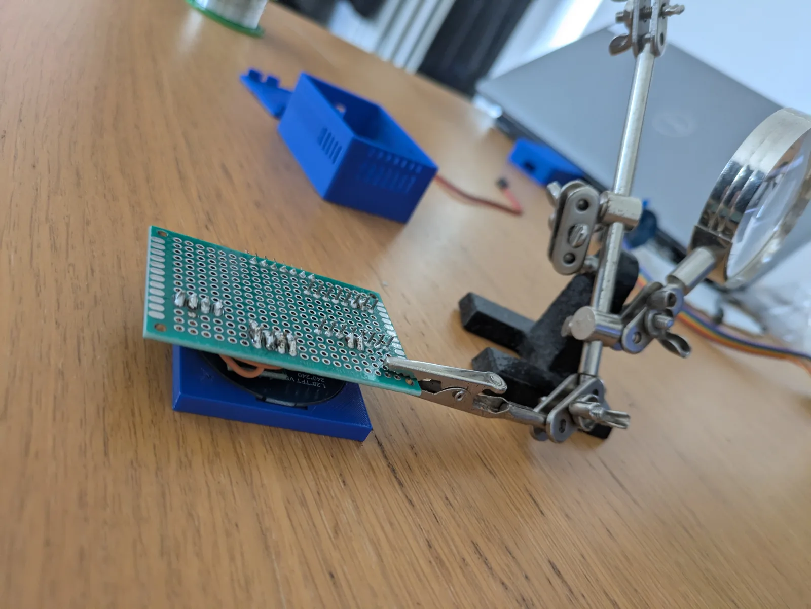
The soldered wiring underneath the perfboard.
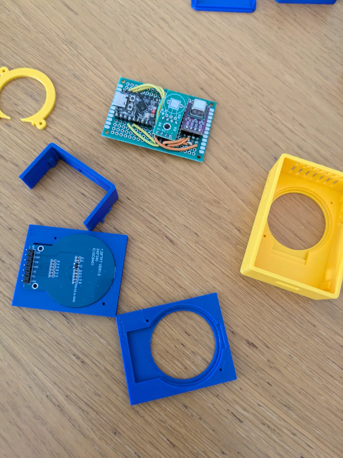
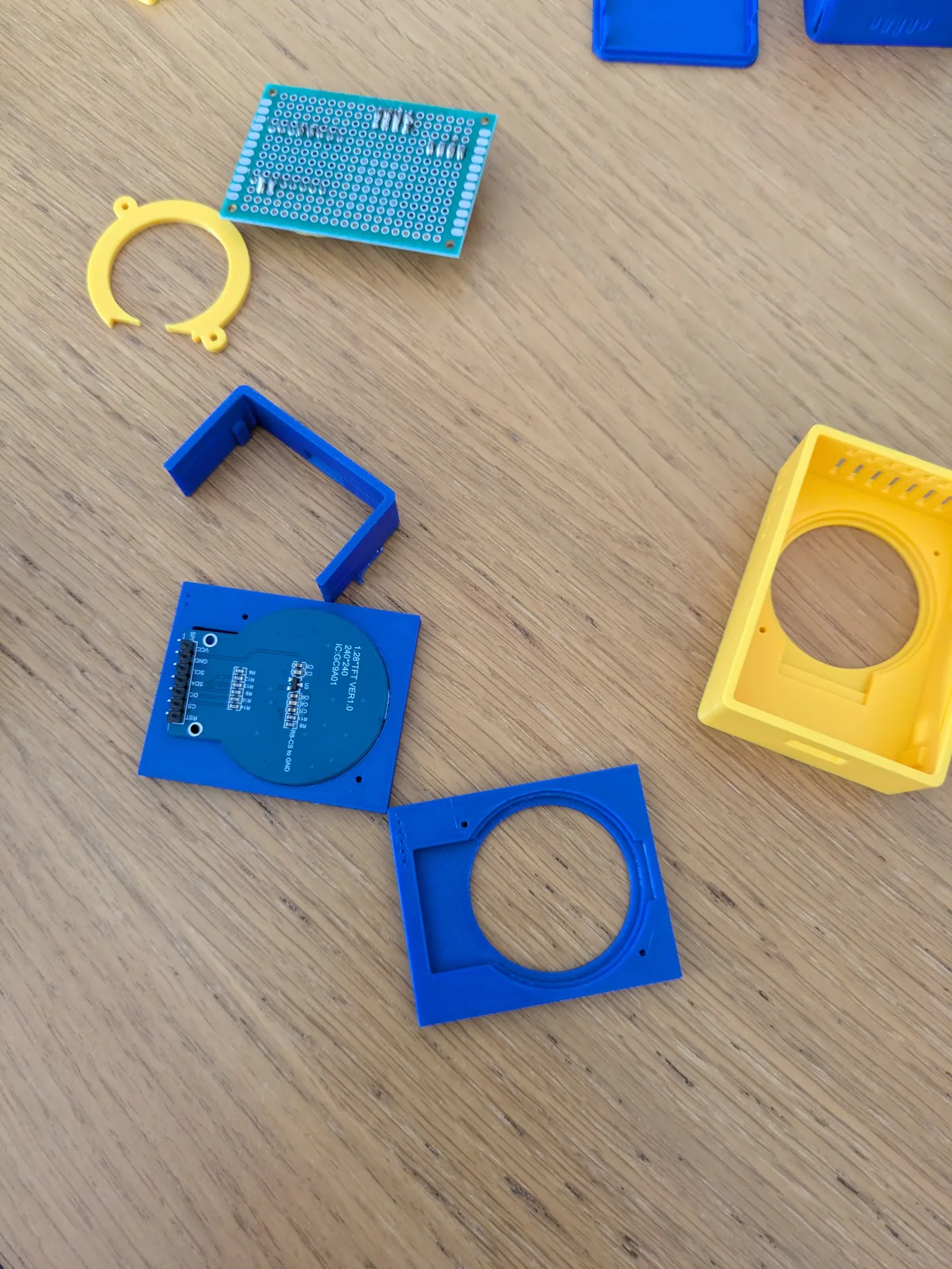
Printed enclosure iterations and the sensor board.
Side view of the blower fit trial.
More build photosLids, soldering and blower trials
Blue enclosure: checking the side clearance.
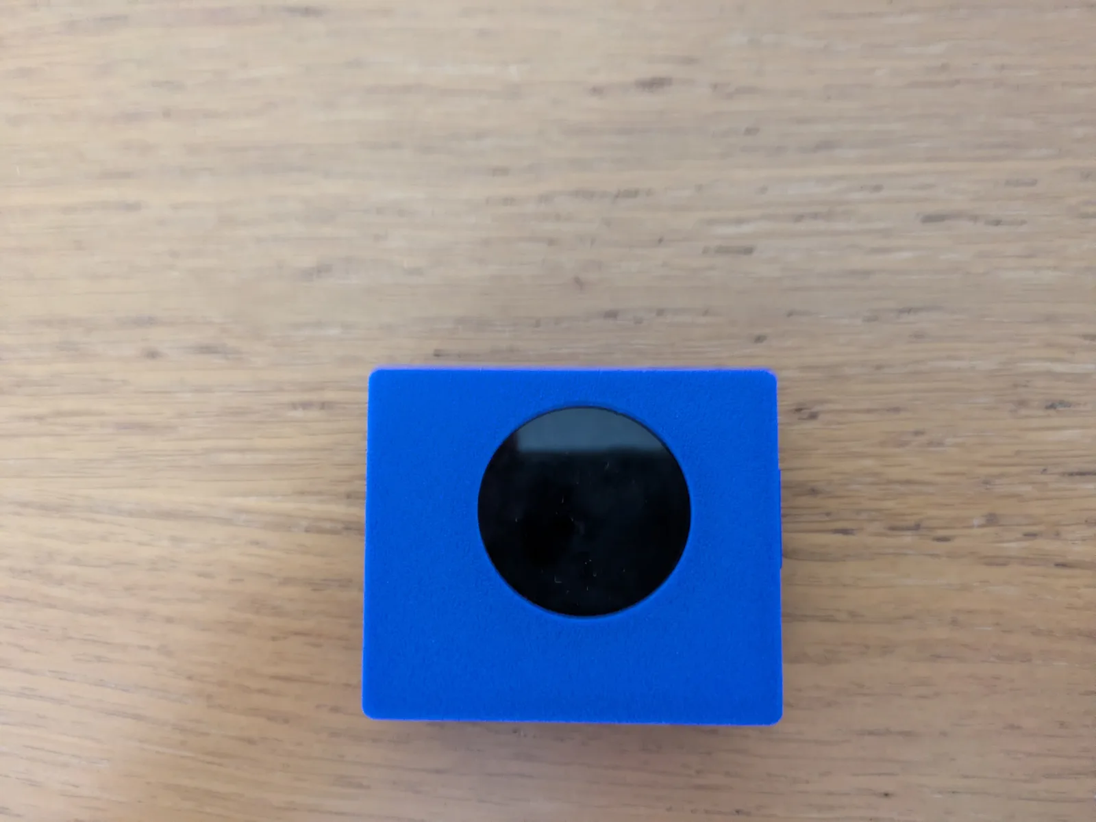
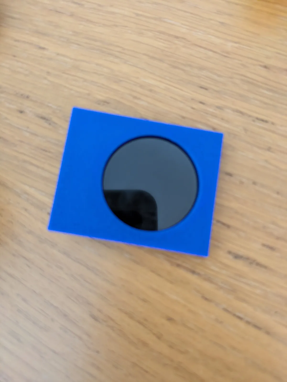
Blue lid and round display, before power-up.
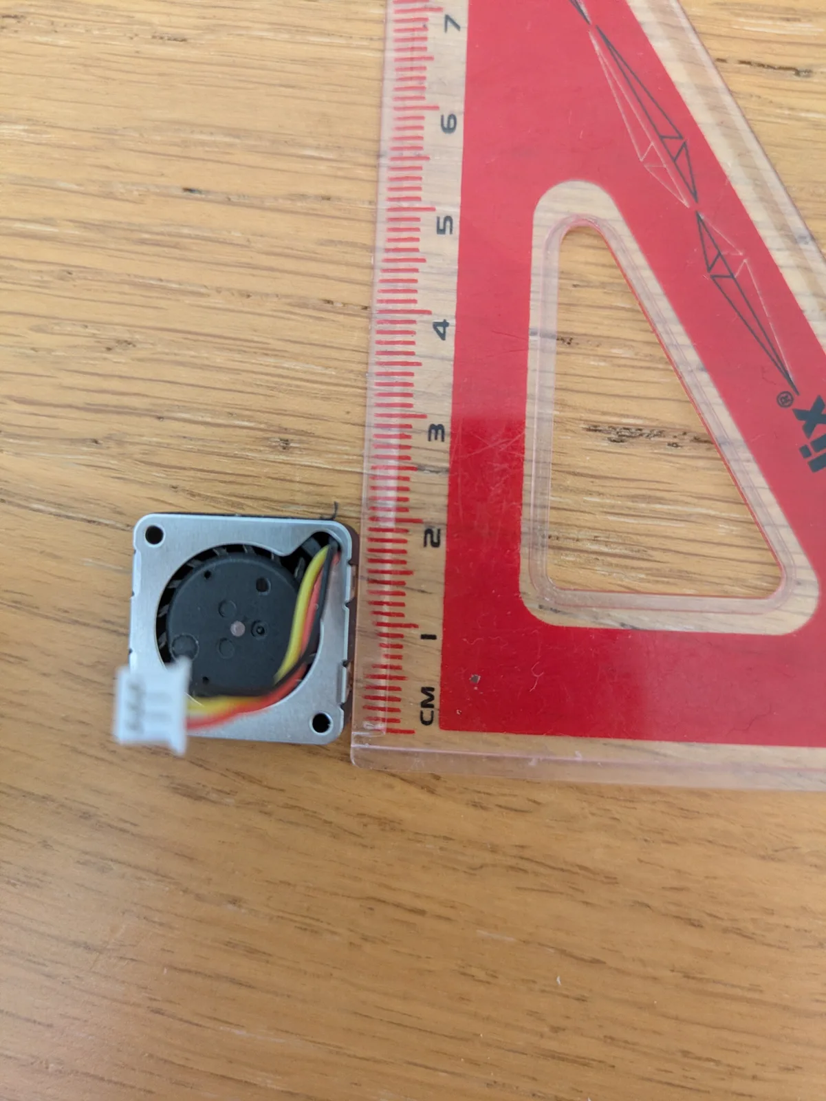
Blower depth beside a ruler.
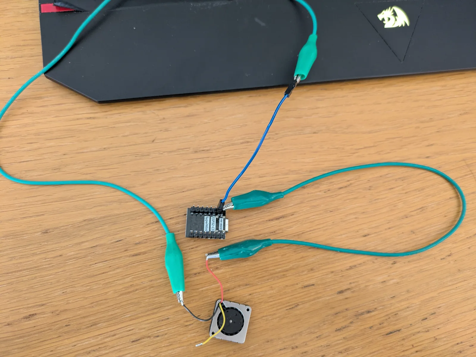
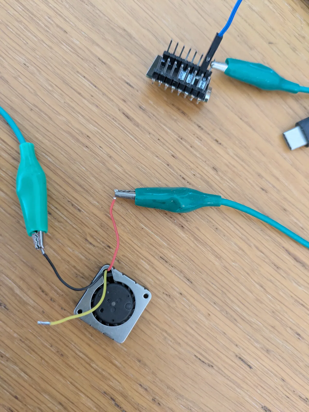
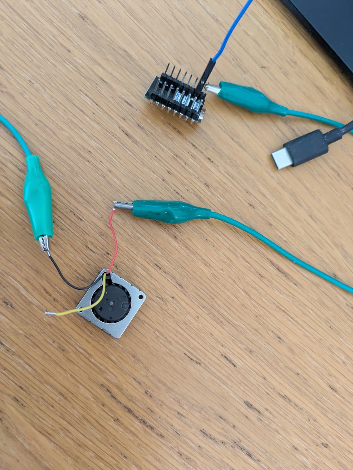
Blower bench wiring with a separate ESP32-C3.
Blower and test connections.
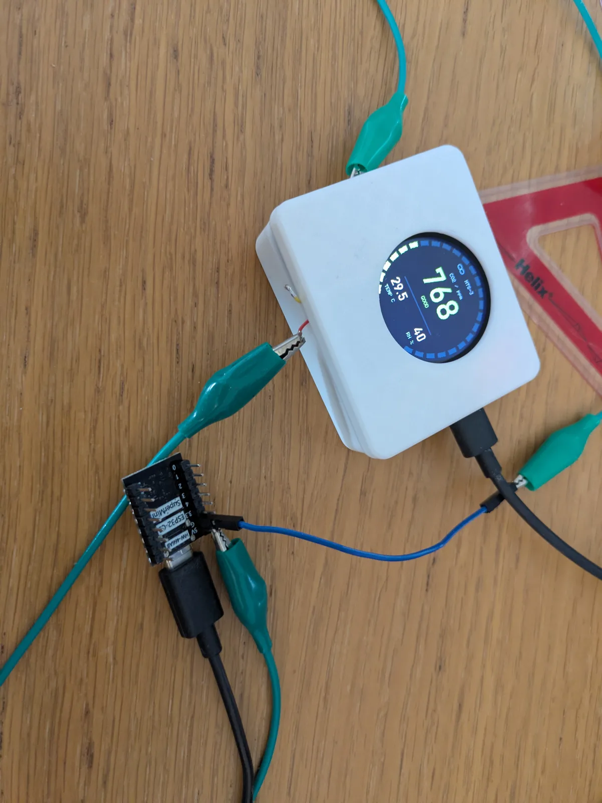
The white build during blower testing.
Blower fit trial in the blue enclosure.
An earlier blue display lid.
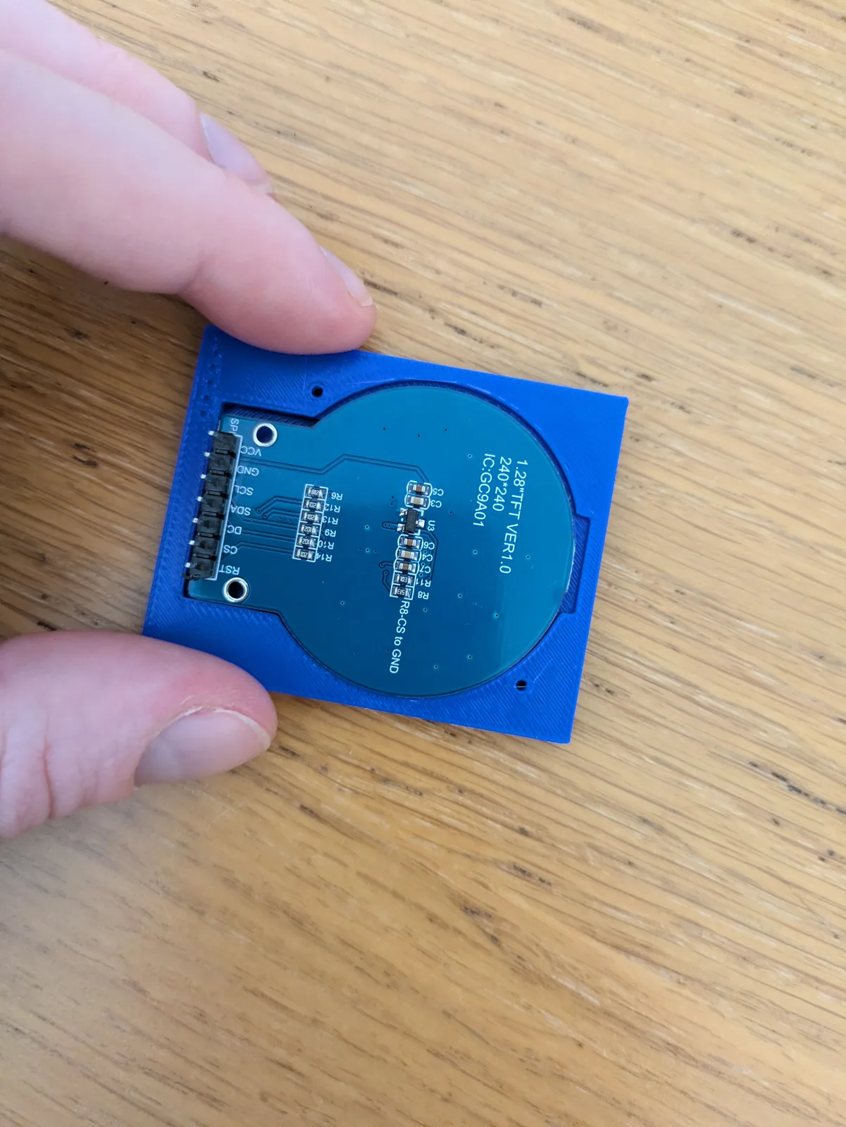
The GC9A01 display seated in the lid.
Soldering the perfboard connections.
Display and sensors assembled on perfboard.
Blue base, sensor board and clip-on lid.
Blower footprint beside a ruler.
USB power and blower test wiring.
Earlier lid, retaining ring and enclosure prints.

EnclosureBuilt around the real board

I measured the assembled board before drawing the enclosure, then printed and adjusted the shell until the sensor openings, lid, and USB-C access all worked with the hardware that was actually on the bench.

Two-part vented sensor enclosure being adjusted in slicer software
The two-part enclosure before printing.
The CO₂ board beside the printed two-part enclosure
The printed shell with the CO₂ board it was made for.

A case with a round display

The current build has a white printed enclosure and a 1.28-inch round display showing CO₂, temperature and humidity. The screen sits above the hand-soldered perfboard, with USB-C power entering on the right. The model at the top follows this setup from the September photos; its dimensions are approximate. The enclosure page keeps the earlier Slab, Gauge and Halo studies alongside the current build.

HeatingThe radiator bridge

A separate ESP32-C3 acts as a Bluetooth bridge for a Terma MOA Blue electric radiator. I used a small probe program to work out how the real controls behaved, then turned that into a bridge between cloud configuration and the radiator’s BLE characteristics.

Requested temperatures are range-checked, written to the radiator, read back, and then reported to the platform. The web interface waits for that device response before it calls a change applied. One radiator has been tested through that complete path; adding another is still future work.

Current stateStill a working project

The sensor, cloud, dashboard, and first radiator-control paths have all been used on the real system. I’m still changing the hardware packaging and the operational side of it, so this page is a record of where the project is now rather than a finished-product claim.