Air-sensor project · enclosure studies
A case for the air sensor
The current white enclosure, with a round display and hand-soldered sensor board. Turn the model or pull it apart to see the layout; the three earlier concepts are here too.
Photo-based model · dimensions approximate · updated
Explore the current build
Drag to turn. Use the slider to separate the parts.

The 3D view needs WebGL, which this browser could not start. The drawing sheets below are generated from the same model and still work.
White build reconstructed from the photos · dimensions approximate · earlier concepts remain in green
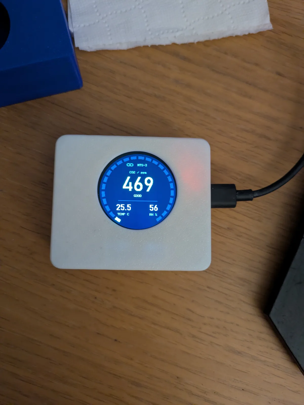
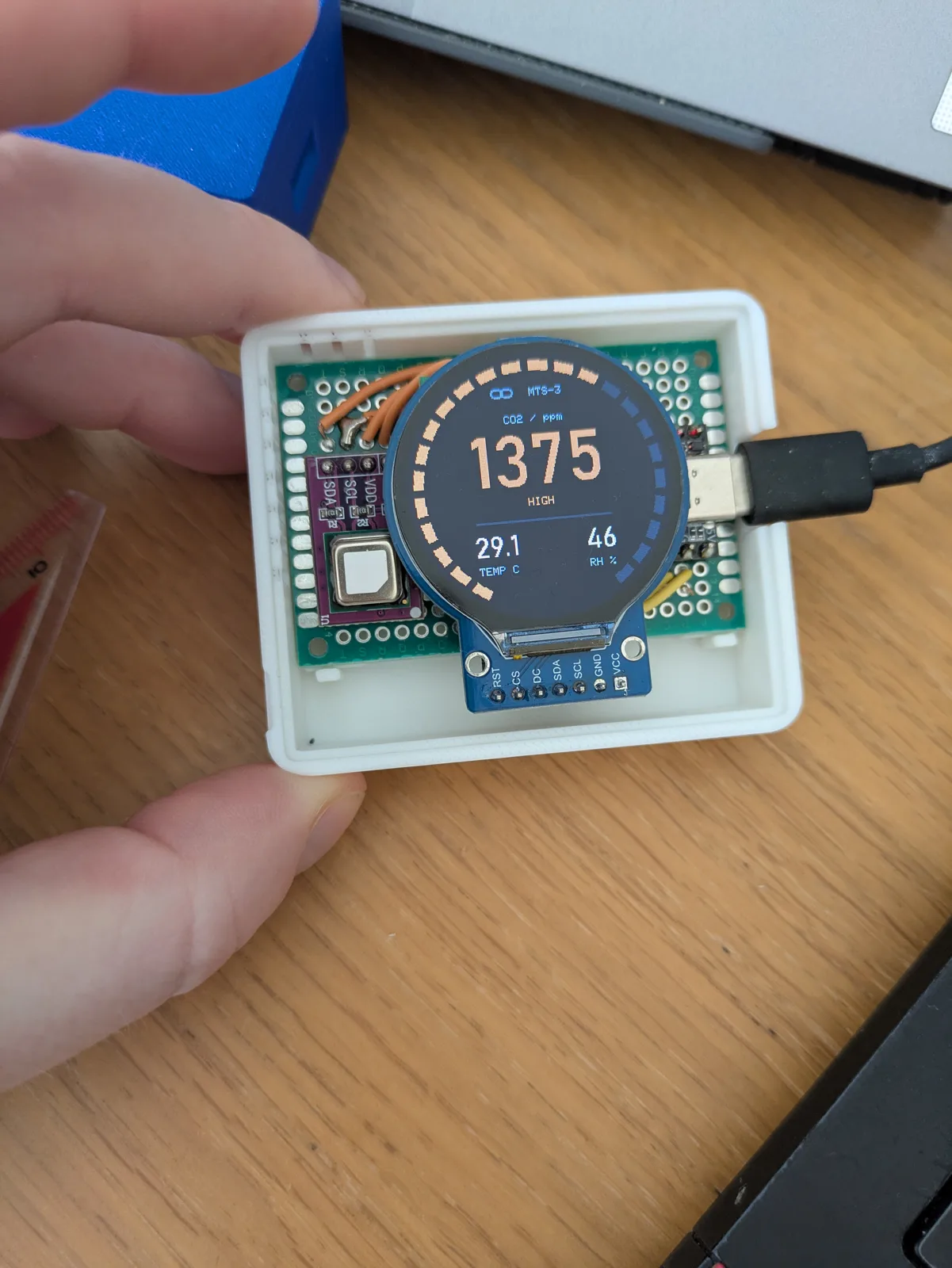
Reference photos of the white build. The model illustrates the visible arrangement, not a print-ready CAD revision. See the assembly and blower-test photos →
Earlier design studies
Open a study for its drawings and sections. The numbers include assumptions that still need checking on the hardware.
A · SlabA flat lid for a bedside table
Concept ASlab
The smallest box the board allows. The display sits in a flat lid directly over the sensor end and reads from above, like a bedside clock. The ESP32-C3 lives under the plain end of the lid with the USB-C leaving through the back wall. Vent slots on three walls sit at the height of the SCD40, so room air crosses the sensor rather than the radio.
B · GaugeAn angled face for a desk
Concept BGauge
A desk instrument. The board lies flat in a low base and the display stands on a front face leaned back twelve degrees, so the CO₂ ring reads from across the room. The face is thicker than the Slab’s lid because the whole display stack is pocketed into it. Height is set by the module itself: the round PCB, its header tab, and a rim to hold it.
C · HaloA round body around the screen
Concept CHalo
The round screen gets a round body. The puck diameter is fixed by the board’s diagonal, which is why it has the largest footprint of the three; in exchange the display is dead centre and the rim carries a continuous band of vent slots. A rectangular bite at the back lets a USB-C plug reach the receptacle, which would otherwise sit too far inside the curve.
Compare the threeDimensions and tradeoffs
ChoiceWhich one to print first
For a bedside table the Slab is the one to print first: smallest, no header surgery, and the display reads from where I lie. The Halo makes sense if the sensor moves to a shelf or desk and the round screen should be the object. The Gauge earns its height only if the reading needs to be visible from the doorway.
What goes insideParts, measurements, and assumptions
PartsComponent census
Every solid part in the model is drawn from these numbers at one common scale of 4 px per mm. The tag on each card says where the number came from: a datasheet or vendor drawing, a measurement from my photos, or an assumption I still need to check with calipers.
Change the earlier studiesBoard, display, wall, and clearances
InputsParameters
Changing an input rebuilds the model, every drawing sheet, and every table. The perfboard measures 4 × 6 cm in my photos; the display PCB diameter is the one number no vendor page states, so it is the first thing to measure.
- Board
- 40 × 60 mm
- Display
- GC9A01 round, Ø32.4 active
- MCU
- ESP32-C3 SuperMini
- Fixings
- M2 screws + heat-set inserts
Before a printFive checks on the actual hardware
Before printingMeasure, then commit
These are design studies rather than a finished part. Nothing here has been printed yet. Five caliper checks turn the studies into printable geometry, and each one maps to a single parameter above.
- Round PCB diameter of the display module, across the circle, not the tab. Sets the pocket and locating ring.
- Perfboard outline corner to corner, and the corner hole spacing. Sets the cavity and standoff positions.
- SCD40 breakout position from the perfboard’s far edge and left edge. It is the tallest part and it sits under the display.
- USB-C height from the perfboard’s underside to the connector’s centreline. Sets the back-wall cutout.
- Header decision: keep the 7-pin header and trim the pins to 3 mm, or desolder it and wire the pads directly. The Slab and Halo sections assume trimmed pins; the Gauge needs the header removed.


